Questions: In the circuit shown in the figure, an ideal ohmmeter is connected across ab with the switch S open. All the connecting leads have negligible resistance. The reading of the ohmmeter will be closest to

In the circuit shown in the figure, an ideal ohmmeter is connected across ab with the switch S open. All the connecting leads have negligible resistance. The reading of the ohmmeter will be closest to
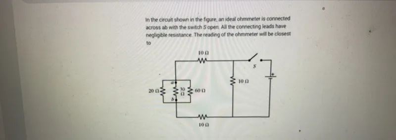
Transcript text: In the circuit shown in the figure, an ideal ohmmeter is connected across ab with the switch $S$ open. All the connecting leads have negligible resistance. The reading of the ohmmeter will be closest to
failed

Solution

failed
failed

Solution Steps

Step 1: Analyze the circuit with the switch open

When the switch S is open, the right part of the circuit containing the 10 Ω resistor and the battery is disconnected. Thus, the ohmmeter only sees the left part of the circuit.

Step 2: Simplify the resistors between a and b

Between points a and b, we have three resistors: 20 Ω, 30 Ω, and 60 Ω. The 30 Ω resistor is in series with the 60 Ω resistor. Their equivalent resistance is \(30 + 60 = 90\) Ω. This 90 Ω equivalent resistance is in parallel with the 20 Ω resistor.

Step 3: Calculate the equivalent resistance

Let the equivalent resistance between a and b be \(R_{ab}\). The formula for parallel resistors is given by: \( \frac{1}{R_{ab}} = \frac{1}{20} + \frac{1}{90} \) \( \frac{1}{R_{ab}} = \frac{90 + 20}{20 \times 90} = \frac{110}{1800} = \frac{11}{180} \) \( R_{ab} = \frac{180}{11} \approx 16.36 \) Ω.

Final Answer

The ohmmeter reading will be closest to \( \boxed{16 \ \Omega} \).

Was this solution helpful?
failed
Unhelpful
failed
Helpful