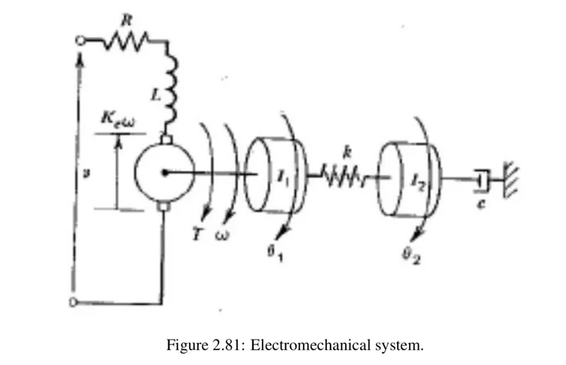
The given figure represents an electromechanical system. Let's define the variables and parameters:
The electrical subsystem can be described by Kirchhoff's voltage law:
\(v = Ri + L \frac{di}{dt} + K_e \omega\)
Also, the torque generated by the motor is proportional to the current:
\(T = K_t i\)
where \(K_t\) is the torque constant. In many cases, \(K_t = K_e\). Therefore, we'll assume \(K_t = K_e\). So:
\(T = K_e i\)
The mechanical subsystem can be described by Newton's second law for rotational motion. For the first rotating mass:
\(J_1 \ddot{\theta}_1 = T - k(\theta_1 - \theta_2)\)
And for the second rotating mass:
\(J_2 \ddot{\theta}_2 = k(\theta_1 - \theta_2) - c\dot{\theta}_2\)
Also, the angular velocity of the motor shaft is equal to the angular velocity of the first rotating mass:
\(\omega = \dot{\theta}_1\)
The governing equations for the electromechanical system are:
Electrical subsystem: \(v = Ri + L \frac{di}{dt} + K_e \dot{\theta}_1\)
Mechanical subsystem: \(J_1 \ddot{\theta}_1 = K_e i - k(\theta_1 - \theta_2)\) \(J_2 \ddot{\theta}_2 = k(\theta_1 - \theta_2) - c\dot{\theta}_2\) \(\omega = \dot{\theta}_1\)
Failed. You've reached the daily limit for free usage.
Please come back tomorrow or visit Solvely.ai for additional homework help.